The power delivery systems in telecom applications now have to cope with large arrays of high-current CPUs, potentially consuming hundreds of watts of power. To increase efficiency, telecom PSUs employ switching topologies to convert electricity from the grid supply to a 48 V DC output that is then distributed to line cards in the rest of the system. The problem is that switched-mode power supplies present nonlinear impedance to the grid because of the structure of their input circuitry.
The input circuit usually comprises a half-wave or full-wave rectifier followed by a storage capacitor that maintains the voltage at a value close to the peak voltage of the input sine wave. It is recharged by the subsequent half wave. This topology only draws current from the input when the grid supply peaks; this pulse contains enough energy to sustain the load until the next peak. The current pulse may last for no longer than a quarter of the cycle, and the current supplied during the pulse must be at least four times the average current.
The resulting current waveform is, compared to the sinusoidal input, heavily distorted with a large number of strong harmonics. Only the fundamental component produces actual power – the remaining peaks are responsible for apparent power. This difference is represented by the power factor, which for all cases, except a pure sine wave, will be less than unity.
The harmonic distortion has an adverse effect on other loads on the same supply. The distorted current causes additional heating in the wires and electrical distribution gear. As a result, legislation has come in worldwide to limit the harmonic distortion of switched-mode PSUs, in addition to controls imposed by the utilities themselves on high-power equipment. Electrical equipment with an input power requirement of 75 W or more, supplied in Europe and Japan, must comply with the IEC61000-3-2 standard. The standard specifies the maximum amplitude of line-frequency harmonics up to and including the 39th harmonic. As core telecom switches are responsible for high loads, they need to limit harmonic distortion and maintain a high power factor.
Power factor correction (PFC) shapes the input current of the PSU to maximize the real power level from the grid and minimize harmonic distortion. Ideally, the electrical appliance should present a load that resembles a resistor rather than the reactive load of a bare switched-mode PSU. Instead of a series of narrow peaks, the current waveform will follow the same sine wave profile as the AC input and will be in phase with it. This corrected waveform minimizes losses as well as interference with other devices being powered from the same source.
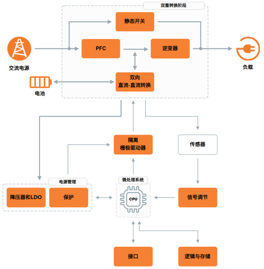
The PSU for a telecom system is generally designed to have a two-stage structure. The front-end stage is used for PFC, while the second stage is a DC/DC conversion circuit that provides the desired regulated DC output. In principle, a simple inductor could provide adequate PFC for many switch-mode PSUs. The inductor acts to spread the current out in time and, in turn, reduces the harmonics far enough to meet most regulations. The drawback is that the inductor needs to be relatively large – its size and cost is generally unacceptable in the context of a densely populated telecom server or switch.

Figure 1: The two-stage architecture of a typical telecom PSU showing the PFC pre-regulator and DC/DC regulator stages.
In practice, the PFC stage in a telecom system is a switched-mode PSU in its own right. The most commonly used topology is that of a boost converter, which adds a switching power-control circuit to the series inductor of a pure passive PFC implementation. The boost converter maintains a continuous input current – this can be forced to track the changes in line voltage to maintain a high power factor. However, within the broad category of boost converters, there are a number of circuit architectures available that provide telecom PSU designers with a high degree of control over efficiency, a key consideration as standards such as Energy Star continue to push losses from PSUs down.
A number of PFC controllers that support continuous conduction – a technique that minimizes current stress – and use average current mode control to achieve a smooth output waveform. International Rectifier’s IR1152 is an average current-mode controller that employs the company’s one-cycle control algorithm.
The one-cycle control algorithm uses two control loops: a slow outer voltage loop and a fast inner current loop. The outer voltage loop monitors a voltage sense pin and generates an error signal that controls the amount of current that is fed into the PFC converter. The inner current loop maintains the desired sinusoidal profile with cycle-by-cycle control over peak current.
The Infineon ICE2PCS02G can switch from continuous conduction mode to discrete conduction mode under light load conditions, which generates higher harmonics but stays within legislative limits and maintains high efficiency. Both the IR1152 and ICE2PCS02G have a number of protection circuits to guard against situations such as brownouts and overvoltage conditions.
An alternative strategy is to use critical, transition, or boundary conduction mode – a scheme that is popular in lower power systems. However, the use of interleaving makes it possible to employ stages in parallel to increase the overall output power and still obtain the advantage of using smaller passive components. Such paralleled converters can operate out of phase to each other to minimize ripple current when summed at the output. This, in turn, reduces the output filtering requirements.

Figure 2: The current generated by the regulator is provided by a series of ramps in boundary conduction mode that follow the profile of the input voltage, scaled to the required power level by a factor of k. In this mode, each ramp starts as soon as the last completes.
In contrast to the continuous conduction mode, the pulse width modulation output that controls current through the circuit does not operate at a fixed frequency. Instead, the error signal provided by the voltage sense channel is used to control when each current pulse should end. At the start of the cycle, the power switch is closed and the boost-converter inductor current ramps up until it reaches the level of the voltage reference. At this point, the power switch is opened and the current ramps down until it reaches zero. When the current in the inductor drops to zero, so will the voltage across it. At this point, the cycle starts again, leading to the name boundary conduction, as the inductor is maintained in a state between continuous and discontinuous conduction, in which the current through the inductor can stay zero for some time.
The L6563 made by STMicroelectronics employs a transition-mode circuit. The device enhances loop stability through the use of a voltage feed-forward function, improving transient response and handling of grid drops and surges. An overvoltage-protection circuit keeps the voltage under control during surges. The L6563 includes support for remote on/off control for systems where the PFC pre-regulator works as a master or as a slave. An interface to the PWM controller of the second-stage DC/DC makes it possible to stop the converter if problems arise with the PFC stage. It also disables the PFC pre-regulator under very light load conditions to prevent efficiency from falling too far.
The Cirrus Logic CS1501 will switch between fully discontinuous and a form of critical conduction. Its normal mode of operation is discontinuous, switching to the quasi-critical mode during peak periods and suited to smaller telecom systems with PSUs rated up to 300 W. Noise-shaping techniques help minimize electrical interference and reduce the size of filtering components.

Figure 3: The CS1501 switches between discontinuous mode and quasi-boundary conduction mode as power requirements change. The current ramps separate in the discontinuous mode.
Traditional continuous conduction mode architectures use a standard, diode-based bridge or half-bridge circuit to rectify the input ahead of the PFC block. However, this bridge typically accounts for losses of around 2 percent under high load conditions. The bridgeless PFC architecture was conceived as a way of eliminating those losses. However, bridgeless approaches generally involve more complex control techniques, and care needs to be taken to avoid generating excessive electromagnetic interference.
One way to work around the complications of the bridgeless topology is to adopt a semi-bridgeless design. With this approach, the PFC inductor is split into two smaller units, each connected to a different switching circuit – one for positive grid voltage and the other for the negative cycle. Diodes are used to link the PFC output ground to the input line and also to provide a return path to prevent the input line voltage from floating relative to ground, which causes problems for the use of the input voltage as a sense input in a fully bridgeless design.

Figure 4: The architecture of a typical semi-bridgeless PFC circuit.
The Texas Instruments UCC28070 is a continuous conduction-mode PFC controller that, by integrating two PWM circuits operating out of phase to each other, suits usage in a semi-bridgeless topology, as well as more conventional interleaved designs. To overcome problems of current sensing, which is more difficult in a bridgeless topology, the UCC28070’s current synthesizer makes it possible to use a combination of on-period sampling and down-slope emulation during the off-period so that the state of the inductor can be recreated during the entire switching cycle.
As the drive for PFC and efficiency continues, we can expect more solutions to appear that combine modes and topologies in novel ways. There are already a variety of implementations from IC suppliers that provide telecom-system designers with a wide range of options.
Summary
This article has provided an overview of techniques for implementing high-efficiency PFC for telecom systems. The devices discussed include products from Cirrus Logic, Infineon Technologies, International Rectifier, STMicroelectronics and Texas Instruments.


