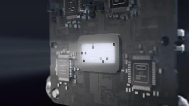
Allegro MicroSystems公司的A6862是N沟功率MOSFET驱动器,具有三个独立的浮置栅极驱动输出,集成的电荷泵控制器稳压器在电源电压降至4.5V时有足够的栅极驱动电压大于7.5V,电源电压4.5V-50V,两个单独的激励输入,单个相位使能输入,主要用在ASIL系统的三相断开,电动助力转向系统(EPS),电制动和三相固态继电器驱动器.本文介绍了A6862主要特性和优势,框图,典型应用框图,以及演示板电路图,材料清单和PCB设计图.
The A6862 is an n-channel power MOSFET driver capable of controlling MOSFETs connected as a 3-phase solid-state relay in phase-isolaTIon applicaTIons. It has three independent floaTIng gate drive outputs to maintain the power MOSFETs in the on-state over the full supply range with high phase-voltage slew rates. An integrated charge pump regulator provides the above battery supply voltage necessary to maintain the power
MOSFETs in the on-state conTInuously when the phase voltage is equal to the battery voltage. The charge pump will maintain sufficient gate drive (>7.5 V) for battery voltages down to 4.5 V with 100 kΩ gate source resistors.
The three gate drives can be controlled by a single logic-level input. In typical applications, the MOSFETs will be switched on within 8 μs and will switch off within 1 μs.
Two independent activation inputs can be used to put the A6862 into a low-power sleep mode with the charge pump disabled. Undervoltage monitors check that the pumped supply voltage and the gate drive outputs are high enough to ensure that the MOSFETs are maintained in a safe conducting state.
The A6862 is supplied in a 16-lead TSSOP (LP) with exposed pad for enhanced thermal dissipation. They are lead (Pb) free, with 100% matte-tin leadframe plating.
A6862主要特性和优势:
• Three floating n-channel MOSFET drives
• Maintains VGS with 100 kΩ gate-source resistors
• Integrated charge pump controller
• 4.5 to 50 V supply voltage operating range
• Two independent activation inputs
• Single phase-enable input
• VCP and VGS undervoltage protection
• 150°C ambient (165°C junction) continuous
A6862应用:
• 3-phase disconnect for ASIL systems up to level D
• Electric power steering (EPS)
• Electric braking
• 3-phase solid-state relay driver

图1. A6862框图

图2. A6862典型应用框图

图3. A6862演示板外形图

图4. A6862演示板电路图
A6862演示板材料清单:


图5. A6862演示板PCB设计图(1)

图6. A6862演示板PCB设计图(2)

图7. A6862演示板PCB设计图(3)

图8. A6862演示板PCB设计图(4)
技术专区
- 当下新能源汽车的两大发展主流
- 汽车电子技术的系统方案及主要功能
- 谷歌车载嵌入式操作系统Android Automotive
- 了解美国电动汽车市场行情及用车习惯
- 无人车公司:2018年于凤凰城推出无人出租车服务


